Example: Layer 2 Engine Inline Interfaces in Passive Engine mode
An example of deploying a Layer 2 Engine in Passive Engine mode in the traffic path.
The administrator at company C wants to set up a Single Layer 2 Engine and deploy it in Passive Engine mode in an inline configuration. The following illustration shows the interfaces of the Single Layer 2 Engine in Passive Engine mode with Inline Interfaces.
Figure: Inline Interfaces in Passive Engine Mode
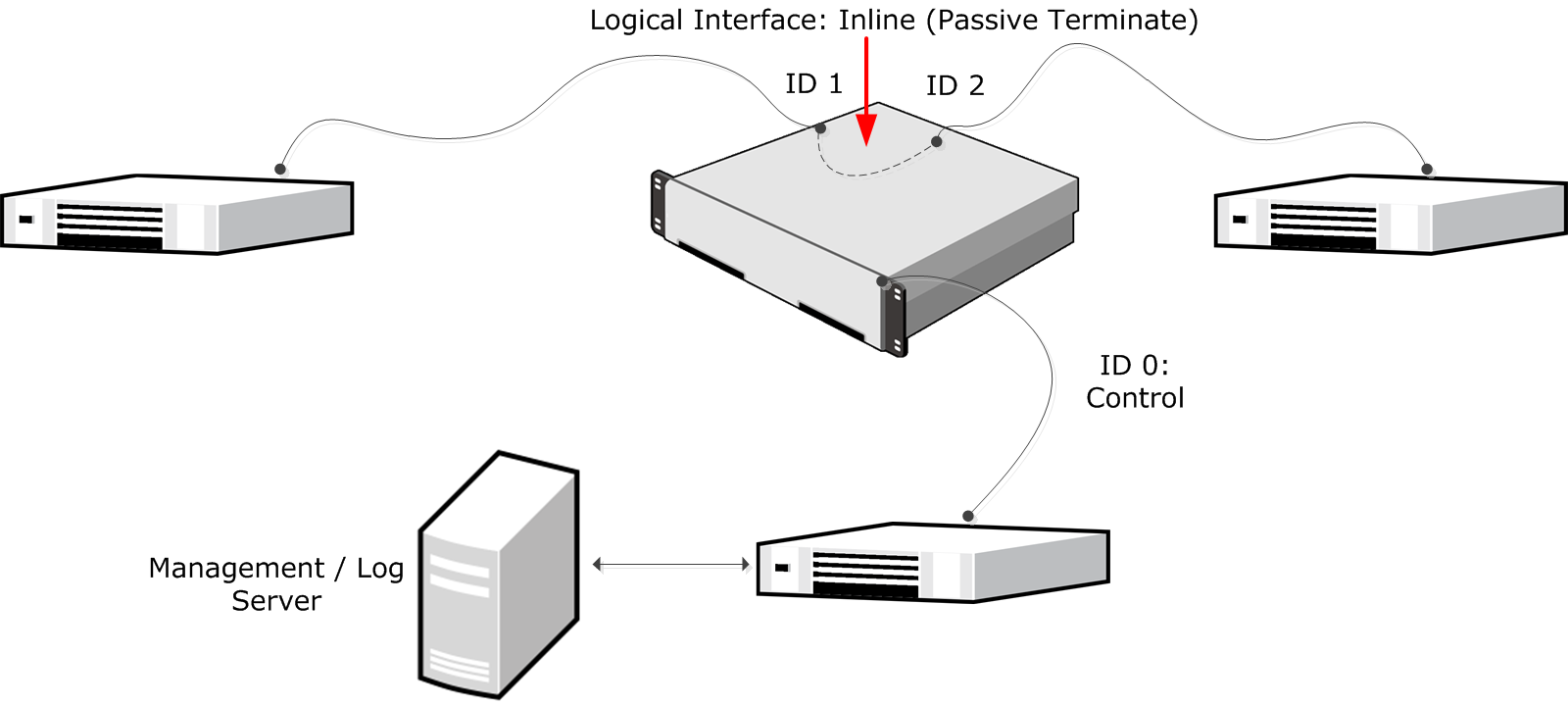
In this example, the IP address on Interface ID 0 is configured as the Control IP address for management connections. Interface ID 1 and Interface ID 2 are an inline interface pair that share the Logical Interface, called Inline (Passive Terminate). Traffic comes in through Interface ID 1 and leaves through Interface ID 2.
The administrator does the following:
- Creates a Single Layer 2 Engine element and selects the Log Server to which the Layer 2 Engine sends its log data.
- Creates a Logical Interface called Inline (Passive Terminate) for the Inline Interface pair.
- Defines Interface ID 0 as a Normal Interface and adds an IP address to it.
- Defines Interface IDs 1 and 2 as an inline interface pair and selects the Logical Interface called Inline for the pair.
- Configures the Layer 2 Engine to only create Terminate (passive) log entries:
- For all connections that match the Access rules with the Discard action in the Layer 2 Engine Policy.
- All Inspection rules with the Terminate action in the Inspection Policy.
- Saves the initial configuration of the engine in the Management Client.
- Connects the network cables to the appropriate physical interfaces on the engine.
- Maps the interface IDs to the physical interfaces in the Secure SD-WAN Configuration Wizard and makes initial contact with the Management Server.
- Installs a Layer 2 Engine Policy in the Management Client to transfer the configuration to the engine.