X10G switch configuration tool
The switch configuration tool allows you to rapidly and accurately configure the X10G switches to support either:
- VLAN with switch high availability
- No VLAN (VLAN-unaware); no support for high availability
Before you begin, download the switch configuration tool to a Windows machine in your network. The Windows machine must be able to connect to the appliance CMC via a web browser. To download the switch tool click here.
Using the tool requires:
- The CMC IP address
- The CMC root password
- If set on either of the switches, the Enable password (not set, by default)
To configure the switch:
- Use the CMC manager to verify that SSH connections are enabled on the page under SSH Configuration.
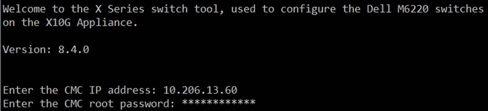
- Navigate to the Windows folder containing the switch configuration tool, and double-click switch-tool.exe to launch the tool.
- When prompted, enter the CMC IP address.
- Enter root as the CMC user name, followed by the root password.
- If an Enable password has been set (not set, by default), enter the Enable password for switch A1, followed by the Enable password for switch A2.
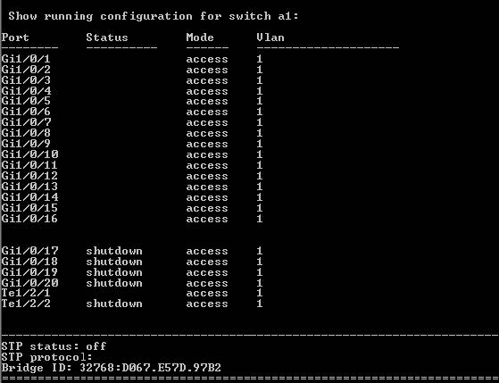
The switch tool displays the current running configuration for switch A1, followed by the configuration for switch A2. For example:
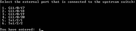
- Select the X10G external port that is connected to your third-party upstream switch. Use option 5 or 6 for VLAN enabled.
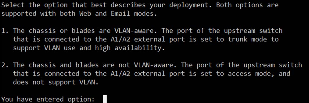
- When prompted to select a deployment option, enter option 1 to enable VLAN support and switch high availability, or option 2 to leave the switch in No VLAN (not VLAN-aware)
mode.
- If you selected option 1:
- Enter the STP priority value for the switches. The recommended value is 57344 (and 61440 on the blades). The STP priority value you set on the upstream switch must be lower (with the effect of making it the root).
- You are prompted to configure VLAN settings for one or more blades. To start, enter the blade number or numbers in a comma-separated list (1,2,3), range format (1-3), or a combination
(1,2, 5-8).
- All of the selected blades will receive traffic for the same VLAN or VLANs.
- After configuring the first blade or set of blades, you will be given the option to configure additional sets of VLAN settings for your remaining blades.
- Enter the VLAN ID or IDs to configure the traffic that will be directed to the selected blades. VLAN IDs can be entered in a comma-separated list (100,101,102), range format (100-102), or a combination. Each blade supports a maximum of 3 VLANs.
- If you have additional blades to configure, enter yes, and repeat steps a and b. When you are finished, enter no to continue with the next step.
- Specify whether to perform a full factory reset before reconfiguring each switch, then review the configuration settings displayed. There is no need to perform a factory reset unless you know there is a problem with the switch configuration.
- If the new settings look correct, enter 1 to start the switch reconfiguration process. Progress information is displayed as first switch A1, then switch A2, is configured. The switch reconfiguration process should take only a few minutes.
- When the switch reconfiguration is complete, press any key to exit the switch configuration tool.
If you have configured for VLAN support, ensure that your upstream switch is configured to send VLAN traffic to the X10G, and then configure individual blades to recognize VLAN traffic. See Configure VLAN support on the blades, for instructions.