Example: IPS Cluster serial inline deployment
This scenario shows an example of an IPS Cluster in a serial inline deployment.
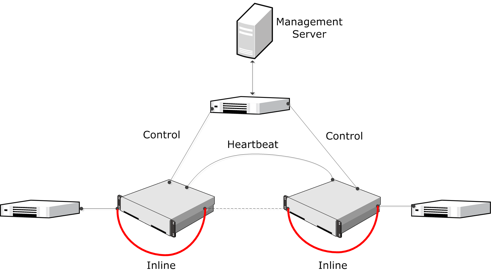
The following illustration shows the interfaces of the inline IPS Cluster.
Figure: Inline serial IPS cluster

In this example, the IPS Cluster consists of two nodes. Interface ID 0 is a Normal Interface used for the heartbeat communication between the nodes. Interface ID 1 is a Normal Interface used for communication with the Management Server. Interface ID 2 and Interface ID 3 are an Inline Interface pair that share one Logical Interface, called Inline. Traffic enters each IPS node through Interface ID 2 and leaves through Interface ID 3.
The administrators:
- Create an IPS Cluster element and select the Log Server to which the IPS Cluster sends event data and traffic recordings.
- Define Interface ID 0 as a Normal Interface and add IP addresses for each of the nodes. The IP address on Interface ID 0 is automatically selected as the Primary Control IP address, the Primary Heartbeat Interface, and the Log communication source IP Address.
- Define Interface ID 1 as a Normal Interface and add IP addresses for each of the nodes.
- Define Interface IDs 2 and 3 as an Inline Interface pair and select the Logical Interface called Inline for the pair.
- Select Interface ID 0 as the Primary Heartbeat Interface and select the IP address on Interface ID 1 as the Primary Control IP address in the Interface Options.
- Save the initial configuration of the engine in the Management Client.
- Connect the Heartbeat and Inline Interfaces between the nodes with crossover cables, and the rest of the interfaces with straight cables.
- Map the interface IDs to the physical interfaces in the Secure SD-WAN Configuration Wizard and make initial contact with the Management Server.
- Install an IPS Policy on each of the nodes in the Management Client to transfer the configuration to the IPS Cluster.