Deployment and test steps to avoid a network loop
When deploying the X10G in a VLAN with high availability, to avoid introducing a network loop, configure the devices and test the configuration in careful steps. Include a network engineer in the configuration and testing of the switches.
Before making any changes, ensure that you have accurate documentation of the current network configuration, as well as the planned, finished configuration.
- The active and planned STP protocols.
- The active and planned STP priority of each switch.
- RSTP - The default protocol on the X10G Dell M6220 switches.
- MSTP - Document the STP priority on each VLAN, including the STP management VLAN. Know the STP priority of each VLAN allowed through the trunk interface.
- PVST* - Document the STP priority on each VLAN, including the STP management VLAN, typically VLAN 1. *If you plan to deploy PVST, it is recommended that you contact Technical Support to review planning and configuration steps.
Recommended configuration and deployment steps.
Steps
-
Ensure that all X10G blade switch interfaces are configured with STP enabled and have root guard enabled. Switch interfaces Gi1/0/1-16 should have a configuration similar
to:
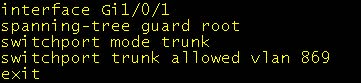
-
When the trunk is up, test that STP is working correctly.
- Log on to the M6220 and run:
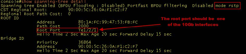
show spanning-tree detailIf spanning tree is working correctly:
- The external switch root’s MAC address is listed in the ROOT ID Address
- One of the 10Gb interfaces is listed as the Root Port.
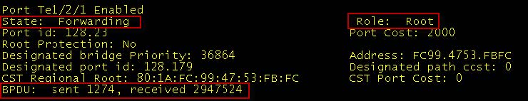
- Check to see if BPDU packets are being sent and received on the uplink port to the external switch. To do this, after running the “show spanning-tree detail” command,
scroll down to the Ten Gig Ethernet interfaces such as Te1/2/1 or Te1/2/2. In the screen capture you can see that BPDU packets are being sent and received. The interface is
also designated as the “root” and is in a “forwarding” state.
- Use “ping” and “ssh” (if enabled on the blade) to test connectivity to the enabled blade.
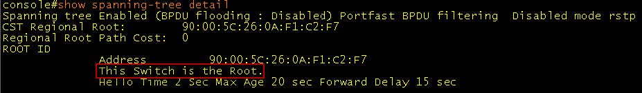
If after running show spanning-tree detail you see the message “This Switch is the Root”, there is a configuration problem. Do not proceed to the next step until you can get the trunk and STP up and confirmed talking with BPDU packets.
- Log on to the M6220 and run: