X10G chassis cabling
How you cable the X10G depends on your planned deployment. Cabling and deployment options are discussed in detail in the X Series Switch Configuration guide. X10G switches can be configured to support VLAN and switch high availability. By default, the switches are not VLAN-aware.
Before finalizing your cable connections, consult with your Forcepoint partner to ensure that your deployment plans are appropriate for your network traffic. See Deployment big picture for related deployment topics and links to other deployment materials.
Power cables, Ethernet cables, a serial cable, and SFP+ cables are shipped with the X10G chassis.
- Note that the 2 on-chassis switches are oriented vertically at the back of the chassis. The switch on the left side is switch A1. The bottom of the switch is shown at the left in the diagram
below. Use an SFP+ cable or install an optical transceiver and use your own fiber optic cable if desired (see details below).
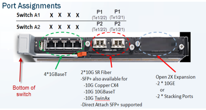
- Fiber optics: If you ordered an optical transceiver kit with your chassis, see the instructions provided here. This allows you to use fiber optic cables to connect the chassis switches to your network. Begin by connecting the P1 interface on switch A1 to your network. The X10G switch requires an LC connector at the end of the optical cable.
- If you are not using fiber optic cables, no transceiver kit is required. Connect an SFP+ cable (provided) to the P1 interface on switch A1.
- While several ports may be labeled on both switches, the only port required for deployment is the P1 port on switch A1. The P2 port on switch A2 is optional and dependent upon your network topology. To ensure correct cabling for your deployment, see the X Series Switch Configuration guide.
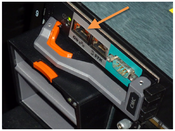
- Next, cable the Chassis Management Controller (CMC). Connect a Category 5 network cable (do not use a crossover cable) from the left-most CMC network port, labeled Gb in the illustration, to a
switch on the subdomain where the CMC IP address is located. The CMC is located at the back of the chassis at the upper left side. Connect the Gb port to the network.
- Use the power cables to connect the 4 on-board power supply units (PSUs) at the bottom (back of chassis) to the power outlets on your computer rack. Ensure that the power cables are
fully inserted into the PSUs and the power source. Confirm that the power lights are illuminated on the PSUs.
- Use the power cables to connect the 4 on-board power supply units (PSUs) at the bottom (back of chassis) to the power outlets on your computer rack. Ensure that the power cables are
fully inserted into the PSUs and the power source. Confirm that the power lights are illuminated on the PSUs.
Power on
Power on the chassis at the front (recessed button at the lower left corner below slots 9 and 10). This powers on all blades. Blades can also be turned off and on individually.